| | Lot's of DevilsThey say the "Devil's in the details". If so, then this project just
got posessed!
But let's back up. Sent email to EV America and ordered the batteries (Trojan
SCS225's). I did this after having a couple productive weekends and finally seeing
the light at the end of the tunnel (right...it was a train). Here's the photo:
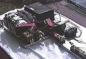
just a few wires here and there, couple more components, no problem.
Ok, so I started adding the last couple of wires. And then a few more. A couple more.
Oh, yeah, forgot these. Hmm, where'd these come from?
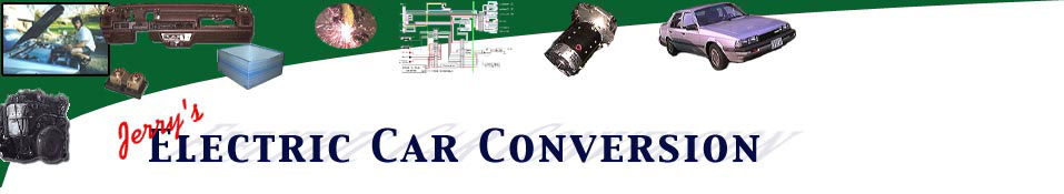
Seemed like everytime I consulted my schematics a new wire showed up from nowhere. Here's
the controller board after those "couple" of wires were added:
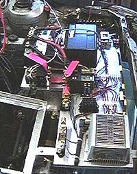
Just a couple more and it's done. Heh, heh.
So after that I decided I needed to make a schematic of all of the
little pieces. Some of this is duplicated elsewhere, but this covers most of
the odds and ends of the control wiring. The 12vdc (in the middle) comes from the offboard
inertia switch, which is connected to 12vdc switched by the ignition key. It also feeds the vacuum pump, which I haven't shown here. The
12vdc leaving the DC-DC converter actually doesn't go directly to the battery, but
follows the same path as the car's old alternator output traveling through a fusible link.
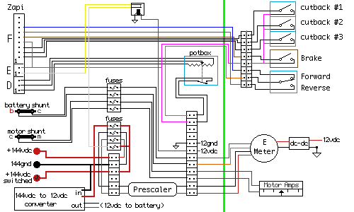
I'll try to explain my nomenclature and symbols:
- The vertical line (light green) shows where the controller board ends and the front
passenger compartment) wiring starts.
- The white boxes with two dots next to each other are wire terminals, where a wire gets screwed
down on one side and one or more wires get connected to the other side. That is, they are are
short from one side to the ot hre
- Not to be confused with the fuse blocks (two dots with a squiggly).
- Towards the upper right, next to all of the switches, is something that looks like a
terminal with a vertical line through it: this is a multipin connector, one end on a wire
bundle from the controller board, the other end is mounted to the back of the switch box.
- The red letters next to the shunts indicate what is hooked to that side: c - controller,
b - battery, m - motor.
- There are two types of 144vdc: one is present all of the time, the other is switched
by the contactors (via the ignition key).
- None of the wires that cross each other are connected: only T junctions.
- The little DC-DC next to the Emeter gets power from the system's 12vdc battery and
turns it into...12vdc. Merely an isolator for safety, etc..
- All of the passenger compartment switches are mounted to the box I showed in
step 25 with the exception of the brake switch. This is the small
micro switch which is mounted DEEP in the guts of the dash (with the loss of much knuckle skin)
against the brake pedal shaft.
Next: More Metal | |
|